DENON DJ MC-6000 MKII
SETUP
Firmware & Drivers
Update the drivers and the firmware of the unit to the latest version from https://www.denondj.com/downloads
Drivers are not required for Mac OSX computers.
VirtualDJ Setup
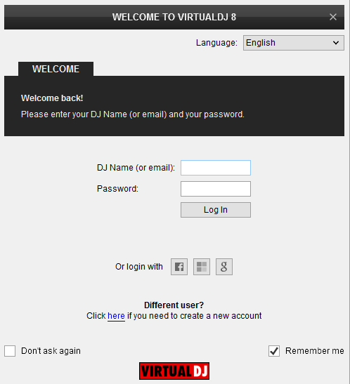
Once VirtualDJ 8 is launched, a Login Window will appear. Login with your virtualdj.com account.
A Pro Infinity or a Pro Subscription License is required to use the Denon MC6000MKII. Without any of the above Licenses, the controller will operate for 10 minutes each time you restart VirtualDJ 8.
http://www.virtualdj.com/buy/index.html
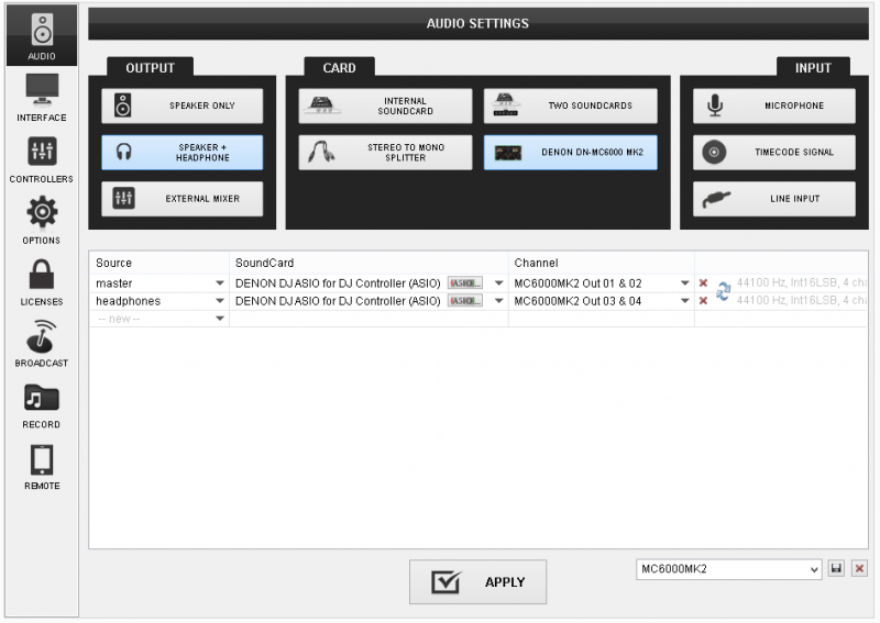
Click on the "Use Soundcard" button and then OK.
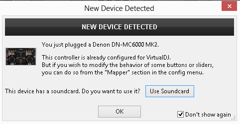
The unit is now ready to operate.
Midi Operation
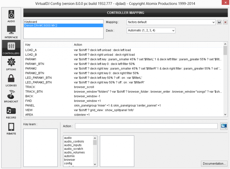
The factory default Mapping offers the functions described in this Manual, however those can be adjusted to your needs via VDJ Script actions.
Find more details at
http://www.virtualdj.com/wiki/VDJ8script.html
AUDIO SETUP
Please read the manual of the unit for further connections/capabilities and setups.
http://b06ba727c886717f9577-fff53f927840131da4fecbedd819996a.r74.cf2.rackcdn.com//1143/documents/MC6000MK2_ENGLISH.pdf
For further VirtualDJ settings and features please refer to the User Guide of VirtualDJ 8.
http://www.virtualdj.com/manuals/virtualdj8/index.html
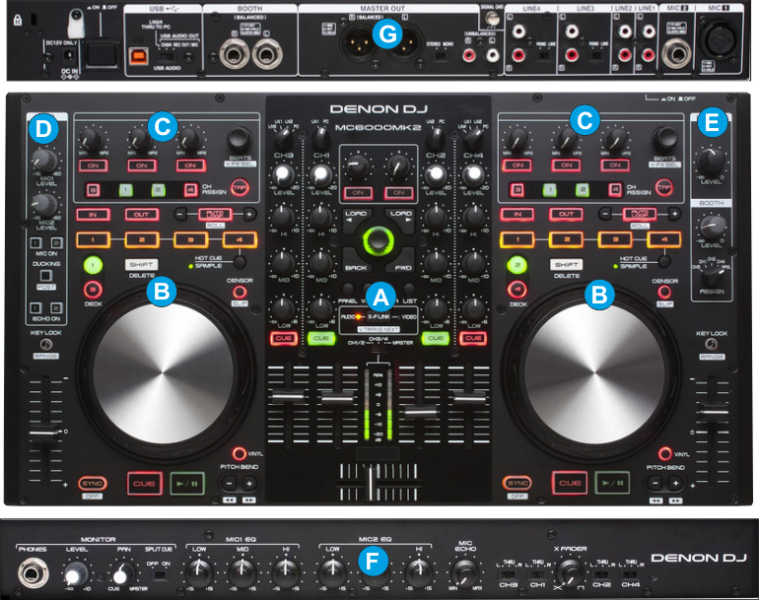
MIXER

- CROSSFADER. Blends audio between the channels assigned to the left and right side of the crossfader.
- VOLUME. Volume Faders (mixer channel order is 3-1-2-4 decks). Note that the faders will not to alter the sound of the corresponding software deck, if the PC-LINE switchers are on LINE positions, but the sound of the software decks will still go through the Master Output.
- CH/MASTER VU. When the switcher is on the MASTER position, the VU meters will show the Output Volume of the Master Output, and will show the Output Level of the corresponding deck if the switcher is on the CH positions.
- CUE/PFL. Press these buttons to send this channel's pre-fader signal to the Cue Channel for monitoring. When engaged, the button will be lit (red for decks 3 and 4 and green for decks 1 and 2).
- EQ LOW. Adjusts low (bass) frequencies of the corresponding channel in the software or hardware Input.
- EQ MID. Adjusts the middle (mid) frequencies of the corresponding channel in the software or hardware Input.
- EQ HI. Adjusts the high (treble) frequencies of the corresponding channel in the software or hardware Input.
- GAIN. Adjusts the audio level (gain) of the corresponding channel in the software or hardware Input.
- INPUT SELECTOR. Set this switch to the desired audio source from this channel: PC (a track playing on that layer in the software), LN1/2/3 (a device connected to the Line Inputs on MC6000MKII rear panel). Note: the software deck will still be outputted on Master Output if the switcher is on LINE positions.
- FILTER. Applies a resonance Filter on the left and right selected software decks.
Hold SHIFT down and then use these knobs to adjust the Key of the left or right selected decks. When the knob is at the zero position (middle), the track will play at its original key. - FILTER ON. Press these buttons to reset the software value of the Filter for the left or right selected decks to zero (off) position. The LED of the buttons will lit if a Filter is applying.
Hold SHIFT down and then press these buttons to reset the key of the left or right selected deck to its original value. - LOAD. Press these buttons to load the selected track from the Browser to the left or right selected deck
Hold SHIFT down and then press this button, to unload the same deck - BROWSE KNOB. Scrolls through Folders or Files. Hold SHIFT down and then use this encoder to adjust the Master Volume of Sampler
BROWSE PUSH. If focus is on the Folders List, push the encoder to enter to the Songs List or hold SHIFT down and then push the encoder to expand/collapse Subfolders.
If focus is on the Songs List, push the encoder to load the selected track from the Songs List to the Automix List or hold SHIFT down and then push the encoder to load the selected track from the Songs List to the Sidelist. - BACK. Sets focus to the previous Browser Window.
- FWD. Sets focus to the next Browser Window.
- BROWSER/SKIN VIEW
- [list]
- PANEL: Press this button to cycle through the available center panels of the Default skins (MIXER, VIDEO, SCRATCH and MASTER)
- VIEW: Press this button to show/hide the File Info window of the VirtualDJ Browser. Hold SHIFT down and then press this button to toggle between the List and Grid Browser views.
- AREA: Press this button to cycle through the available Sideview windows (Automix, Sidelist, Sampler, Karaoke and Clone).
- LIST: Press this button to show/hide the Sideview window of VirtualDJ Browser.
- XF-LINK. Each time this button is pressed, the crossfader (1) will control the Audio, the Video or both crossfaders of VirtualDJ. The leds on the sides of the button indicate the selected mode.
Note that if the LINK (Video Crossfader Link action) from the VIDEO center panel of the default skin of VirtualDJ is enabled, the crossfader of the MC6000MKII will still control both audio and video crossfaders even if the XF-LINK button is on the AUDIO position.
DECK CONTROLS
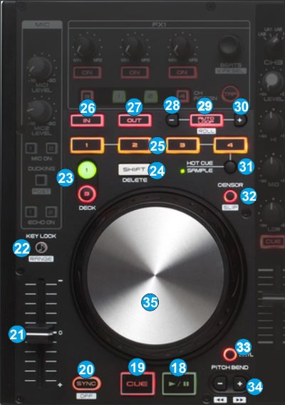
- PLAY. Plays / Pauses the track.
- CUE. When the Deck is paused, you can set a temporary Cue Point by moving the Platter to place the Audio Pointer at the desired location and then pressing the Cue Button.
During playback, you can press the Cue Button to return the track to this Cue Point. (If you did not set a Cue Point, then it will return to the beginning of the track.).
If the Deck is paused, you can press and hold the Cue Button to play the track from the Temporary Cue Point. Releasing the Cue Button will return the track to the temporary Cue Point and pause it. To continue playback without returning to the Temporary Cue Point, press and hold the Cue Button, then press and hold the Play Button, and then release both buttons. - SYNC. Press this button to automatically match the corresponding Deck's tempo with the opposite Deck's (or the Master Deck’s if using a 4 decks Skin) tempo and phase. Press and hold Shift and press this button to set this deck as Master Deck.
- PITCH. Adjust the track's playback speed (tempo).
The actual pitch fader will not alter the pitch of the track if the actual pitch and the software pitch value do not match (software soft-takeover, ghost fader visible on the GUI). In most cases this may happen if SYNC is prior pressed or switching decks and the other deck is having a different pitch software value. - KEYLOCK. Press this button to "lock" the track's pitch to its original key. The track's tempo will remain at the speed designated by the Pitch Fader.
Hold SHIFT down and then press this button to adjust the range of the Pitch Fader ( to ±6%, ±8%, ±10%, ±12%, ±20%, ±25%, ±33%, ±50%, and ±100%).
The Led of the KEYLOCK will blink when the left or right decks are switched and the selected deck is having a different pitch value than the previous and will stop if the pitch fader meets that value (hardware soft-takeover, not visible on the GUI). - DECK SELECT. Switch Left decks (1 and 3) and Right Decks (2 and 4). The left side of the MC6000MKII will control VirtualDJ decks 1 or 3, and the right side will control VirtualDJ decks 2 or 4.
- SHIFT. Press and hold this button to access secondary functions (mainly in white lettering) of other controls on the MC6000MKII
- HOTCUE/SAMPLER BUT. These 4 buttons offer a different function depending on the selected mode (31).
In HotCue mode the 4 buttons assign a Hot Cue Point (1 to 4) or returns the track to that Hot Cue Point. When a Hot Cue Button is unlit, you can assign a Hot Cue Point by pressing it at the desired point in your track. Once it is assigned, the Hot Cue Button will light. To return to that Hot Cue Point, simply press it.
Press and hold SHIFT and then press a Hot Cue Button to delete its assigned Hot Cue Point.
In Sampler mode, the 4 buttons will trigger a Sample from the selected Bank of VirtualDJ. If the selected bank has less than 5 samples (slots), both sides of the MC6000MKII will control the same samples. If a bank has more than 4 samples (slots), the left side of the MC6000MKII will control samples 1 to 4 and the right side samples 5 to 8.
Hold SHIFT down and then press a button to stop the corresponding sample (useful if the selected Sampler Trigger mode is set to Stutter or Unmute) - LOOP IN. Press this button to set a Loop In (Entry point).
Hold SHIFT down and then press this button to set the Jogwheel to Loop In mode and (fine) adjust the Loop In point using the jog when a loop is enabled. The Led of the button will blink to indicate the Loop In Wheel mode. Press again to return the Jogwheel to Jog mode. - LOOP OUT. Press this button to set the Loop Out (Exit point).
Hold SHIFT down and then press this button to set the Jogwheel to Loop Out mode and (fine) adjust the Loop Out point using the jog when a loop is enabled. The Led of the button will blink to indicate the Loop Out Wheel mode. Press again to return the Jogwheel to Jog mode. - LOOP-. Press this button to half the size (in beats) of the Loop.
In Sampler Mode, hold the HOTCUE/SAMPLER mode button (31) down and then use this button to half the size of the Sampler Loop (in case the Sample is in Loop mode) - AUTOLOOP. Press this button to enable/disable a Loop of the selected size.
Hold SHIFT down and then hold this button down to trigger a Loop Roll (momentary). While both buttons are held, use the LOOP-(28) and LOOP+(30) buttons to half or double the size of the Loop Roll. - LOOP+. Press this button to double the size (in beats) of the Loop.
In Sampler Mode, hold the HOTCUE/SAMPLER mode button (31) down and then use this button to double the size of the Sampler Loop (in case the Sample is in Loop mode) - HOTCUE/SAMPLER MODE. Use this button to select the HotCue or Sampler mode for the HotCue/sampler buttons (25).
- CENSOR. Hold this button down to play the track in reverse. When released the track will continue to play from the position it would have been if the button was never pressed (censor).
Hold SHIFT down and then press this button to enable/disable Slip mode. When Slip mode is enabled several actions like HotCues, Loops and scratching with the Jogwheel will act temporary and the track will return to the position it would have been if the Slip mode was never enabled. - VINYL. Press this button to set the Jogwheel to Vinyl (Scratch) or CD (Bend) mode. In Vinyl mode, use the outer part of the Jogwheel to bend (temporary speed up – slow down the tempo of the track).
- PITCH BEND. Press and hold down these buttons to temporary speed up/slow down the song while pressed. When released, the track playback will return to the speed designated by the Pitch Fader.
Hold SHIFT down and then use these buttons to move the track backwards/forward by 4 beats.(seek) - JOG. Touch sensitive jogwheel. Use the jogwheel to scratch (if Vinyl mode is selected) or pitch bend. Hold SHIFT down and then use the jogwheel to fast seek through the track.
When a Loop is enabled, hold SHIFT down and then use the jogwheel to move the Loop forward or backwards through the track. The Jogwheel also offers Loop In and Loop Out point adjustment (see LoopIn, LoopOut buttons)
EFFECTS
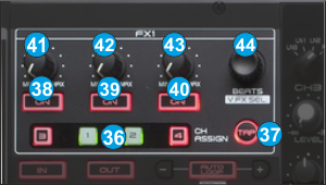
- FX CH ASSIGN (per Deck). Use these buttons to clone the effects from the corresponding deck to the current left or right deck.
The FX units 1 and 2 will apply the selected/triggered Effects to the left and right deck respectively.
- BEAT TAP. Manually adjust the tempo of the song. Tap this button at the same tempo as the track to help the software detect a different BPM reading (if needed).
Hold SHIFT down and then press this button to set the left or right Effects unit to Single or Multi Effects mode. The Led of the TAP button will be on in Multi Effects mode to indicate the selection.
Note. If the default skin is used with VirtualDJ 8, the Effects section will change according to the mode to offer 1 or 3 FX slots. - FXON 1 button
In Single FX Mode, press this button to trigger the selected Effect.
In Multi FX Mode, press this button to trigger the selected Effect on FX Slot 1. Hold SHIFT down and then press this button to select the next Effect for FX Slot 1. - FXON 2 button
In Single FX Mode, press this button to control the Effect button 1 of the selected Effect (if the Effect offers one)
In Multi FX Mode, press this button to trigger the selected Effect on FX Slot 2. Hold SHIFT down and then press this button to select the next Effect for FX Slot 2. - FXON 3 button
In Single FX Mode, press this button to control the Effect button 2 of the selected Effect (if the Effect offers one)
In Multi FX Mode, press this button to trigger the selected Effect on FX Slot 3. Hold SHIFT down and then press this button to select the next Effect for FX Slot 3. - FX 1 knob.
In Single FX Mode, use this knob to select an Effect.
In Multi-FX Mode, use this knob to control the 1st parameter of the selected Effect on FX Slot 1. Hold SHIFT down and then use this knob to control the 2nd parameter of the selected Effect on FX Slot 1. - FX 2 knob.
In Single FX Mode, use this knob to control the 1st parameter of the selected Effect. Hold SHIFT down and then use this knob to control the 3rd parameter of the selected Effect.
In Multi-FX Mode, use this knob to control the 1st parameter of the selected Effect on FX Slot 2. Hold SHIFT down and then use this knob to control the 2nd parameter of the selected Effect on FX Slot 2. - FX 3 Knob.
In Single FX Mode, use this knob to control the 2nd parameter of the selected Effect. Hold SHIFT down and then use this knob to control the 4th parameter of the selected Effect.
In Multi-FX Mode, use this knob to control the 1st parameter of the selected Effect on FX Slot 3. Hold SHIFT down and then use this knob to control the 2nd parameter of the selected Effect on FX Slot 3. - BEATS Encoder. This encoder moves forward/backwards the track by 1 beat. Push the Encoder to show/hide the FX GUI of the selected Effect (of slot 1).
Hold SHIFT down and then use the encoder of the left side (FX1 unit) to select a Video Transition. Hold SHIFT down and then push the left encoder to trigger the selected Video Transition.
Hold SHIFT down and then use the encoder of the right side (FX2 unit) to select a Master Video Effect. Hold SHIFT down and then push the right encoder to trigger the selected Master Video Effect.
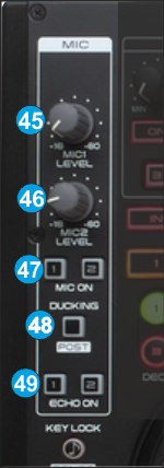
MICROPHONE
 The Denon MC6000MKII offers 2 Microphone Inputs. Both route and control those Inputs in Hardware mode and cannot be controlled or assigned to any VirtualDJ actions, therefore none of these buttons and sliders will move/control any microphone elements on the VirtualDJ GUI.
 However, the entire Microphone section is capable to send Midi messages and can be assigned to any VirtualDJ script action in case the Microphone inputs are not required to your style of mixing.
- MIC1 LEVEL. Adjust the Volume of the Microphone 1 Input of the MC6000MKII (rear connection)
- MIC2 LEVEL. Adjust the Volume of the Microphone 2 Input of the MC6000MKII (rear connection)
- MIC ON. Turn On/Off the Microphone 1 and 2 Inputs of the unit.
- DUCKING. Press this button in order the Volume of the Master Output to drop while the Microphone is used (and turned On).
- ECHO ON. Apply an Echo Effect to the Microphone Inputs. The Level of the applied Echo Effect is controlled from the front side of the unit.
MASTER & BOOTH
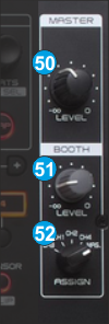
- MASTER LEVEL: Adjusts the Master Output Volume (Hardware operation. Movement will not be visible on the VirtualDJ GUI, nor will control the internal mixer Master Volume)
- BOOTH VOLUME. Adjusts the Booth Output Volume (Hardware operation. Movement will not be visible on the VirtualDJ GUI, nor will control the internal mixer Booth Volume)
- BOOTH ASSIGN. Choose if a specific mixer channel or the Master Output will be routed to the Booth Output.
Front Panel
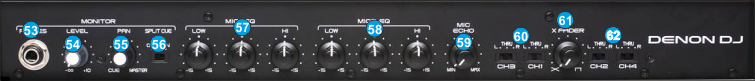
- PHONES SOCKET. Connect your 1/4" headphones to this output for cueing and mix monitoring.
- MONITOR LEVEL. Adjusts the volume level of the headphone output. Hardware operation, movement not visible on the VirtualDJ GUI
- MONITOR PAN: Turn to mix between Cue and Master in the Headphone channel. When all the way to the left, only channels routed to Cue will be heard. When all the way to the right, only the Master Output will be heard. Hardware operation, movement not visible on the VirtualDJ GUI
- MONITOR SPLIT. When this switch is in the ON position, the headphone audio will be "split" such that all channels sent to Cue are mixed to mono and applied to the left headphone channel and the Master Output is mixed to mono and applied to the right channel. When the switch is in the OFF position, Cue and Master Output audio will be "blended" together.
- MIC1 EQ. Adjust the Low (Bass), Mid (Middle) and High (Treble) frequencies of the Microphone Input 1. Hardware operation, movement not visible on the VirtualDJ GUI
- MIC2 EQ. Adjust the Low (Bass), Mid (Middle) and High (Treble) frequencies of the Microphone Input 2. Hardware operation, movement not visible on the VirtualDJ GUI
- MIC ECHO LEVEL. Adjust the strength of the applied Echo Effect on both Microphone Inputs (if the ECHO is enabled from the MIC ECHO buttons (49)).
- X-FADER CH LEFT ASSIGN. Routes the audio playing on the corresponding channel 1 or 3 to either side of the crossfader (A or B), or bypasses the crossfader and sends the audio directly to the Master Output (center, THRU)..
- XFADER CURVE. Adjusts the slope of the crossfader curve. Turn the knob to the left for a smooth fade (mixing) or to the right for a sharp cut (scratching). The center position is a typical setting for club performances.
- X-FADER CH RIGHT ASSIGN. Routes the audio playing on the corresponding channel 2 or 4 to either side of the crossfader (A or B), or bypasses the crossfader and sends the audio directly to the Program Mix (center, THRU).
Rear Panel
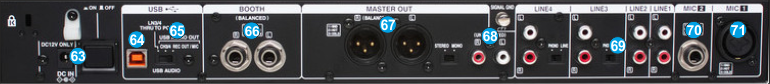
- POWER: Use the included power adaptor to connect MC6000MKII to a power outlet. While the power is switched off, plug the cable into MC6000MKII first, and then plug the cable into a power outlet. Use the Power Switch to turn the MC6000MKII on and off. Turn on MC6000MKII after all input devices have been connected and before you turn on amplifiers. Turn off amplifiers before you turn off MC6000MKII.
- USB. This USB connection sends and receives audio and control information from a connected computer.
- USB AUDIO MODE. Define how the Inputs of the MC6000MKII audio interface are routed to the computer. See Advanced Audio Setup
- BOOTH OUTPUT (BALANCED): Use standard TRS cables to connect this output to a booth monitoring system. The level of this output is controlled by the Booth knob on the top panel.
- MASTER OUTPUT (XLR): Connect this low-impedance XLR output to a PA system or powered monitors. The level of this output is controlled with the Master knob on the top panel.
- MASTER OUTPUT (RCA): Use standard RCA cables to connect this output to a speaker or amplifier system. The level of this output is controlled by the Master knob on the top panel.
- LINE INPUTS. Connect your audio sources to these inputs. Inputs 1 and 2 can accept both line and phono-level signals.
- MIC 2 INPUT. Connect a 1/4" microphone to this input. Microphone controls are located on the top Microphone panel.
- MIC 1 INPUT. Connect a 1/4" microphone to this input. Microphone controls are located on the top Microphone panel.
Advanced Audio Setup
The Denon MC6000MKII offers 3 modes for the USB Audio Inputs selected by the switcher (65) at the rear side of the unit. The modes can be selected/switched without re-launching VirtualDJ or power cycling the unit.
REC OUT/MIC
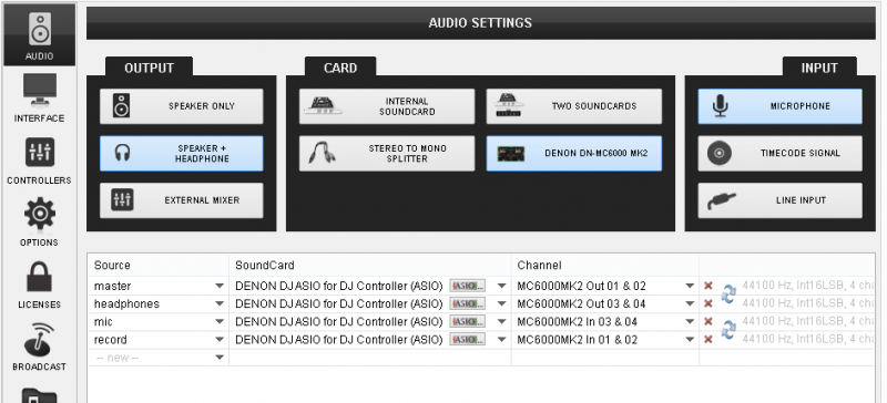
This mode outputs signals for the REC OUT and MIC input to the computer. When you set the USB Audio Output Source Select Switcher (65) to ‘REC OUT/MIC’ position, the audio signals from the USB audio output terminal are set as follows.
- REC OUT output: Output from the USB 1/2 channels to the computer.
- MIC input: Output from the USB 3/4 channels to the computer.
Use this mode to record the Master Output of VirtualDJ, the auxiliary sources (connected to the Line Inputs) and the Microphone Inputs as well.
Go to the AUDIO tab of VirtualDJ config and create the following audio setup.
INPUT CH3/4
This mode outputs signals for the input channels 3/4 to the computer. When you set the USB Audio Output Source Select Switcher (65) to ‘CH3/4’ position, the audio signals from the USB audio output terminal are set as follows.
- Input channel 3: Output from the USB 1/2 channels to the computer.
- Input channel 4: Output from the USB 3/4 channels to the computer.
Use this mode to pass the auxiliary media sources connected to the Line Inputs 3 and 4 to VirtualDJ.
Go to the AUDIO tab of VirtualDJ config and create the following audio setup.
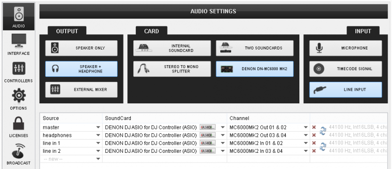
Use the smart buttons on the 4 decks default skin (assigned as deck left linein 1 and deck right linein 2)
LN3/4 THRU to PC
This mode outputs signals for the input channels 3/4 to the computer directly without passing through the mixer of the MC6000MKII (Useful for Timecode Setup - DVS).
. When you set the USB Audio Output Source Select Switcher (65) to ‘LN3/4 THRU’ position, the audio signals from the USB audio output terminal are set as follows.
- LINE3: Output from the USB 1/2 channels to the computer.
- LINE4: Output from the USB 3/4 channels to the computer.
Use this mode to control one or more VirtualDJ decks with Timecode CDs or Vinyls. Connect your CD players or your Turntables to the Line Inputs 3 and 4.
Go to the AUDIO tab of VirtualDJ config and create the following audio setup.
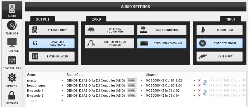
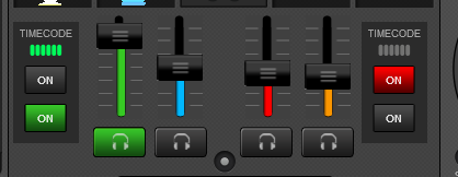 Once the Timecode Inputs are set as above in the Audio setup, the TIMECODE panels will appear at the SCRATCH center panel of the default 4 deck skin.
 Use the ON buttons to enable the timecode control to any of the 4 software decks.
Note. Timecode function requires a Pro Infinity license
